Did it happen that you did not know where to start digging or ripping the wall? With our sonde locating wands the task of detecting the sonde beacon is simplified. Check them out and choose yours.
512Hz Sonde Locators
Sonde Locators
Underground Locating Devices
+ Full Specifications
XT512 Portable Sonde Locator
— Operates on 512Hz frequency mode
— Passive detection of 50Hz or 60Hz, and sonde
— One-button digital depth measurement
— Weights under 2.8lbs
— Audio & Visual Indication Outputs
— Battery & Sensitivity Indicators
— Small for easy storage
— Battery Life: 12 hours (intermittent use)
— Peak and null readings for exact pinpointing
— Max depth reading: Typical 5-8' (1.5 - 2.5 m) dependent on signal level emitted by sonde
— Made in the USA
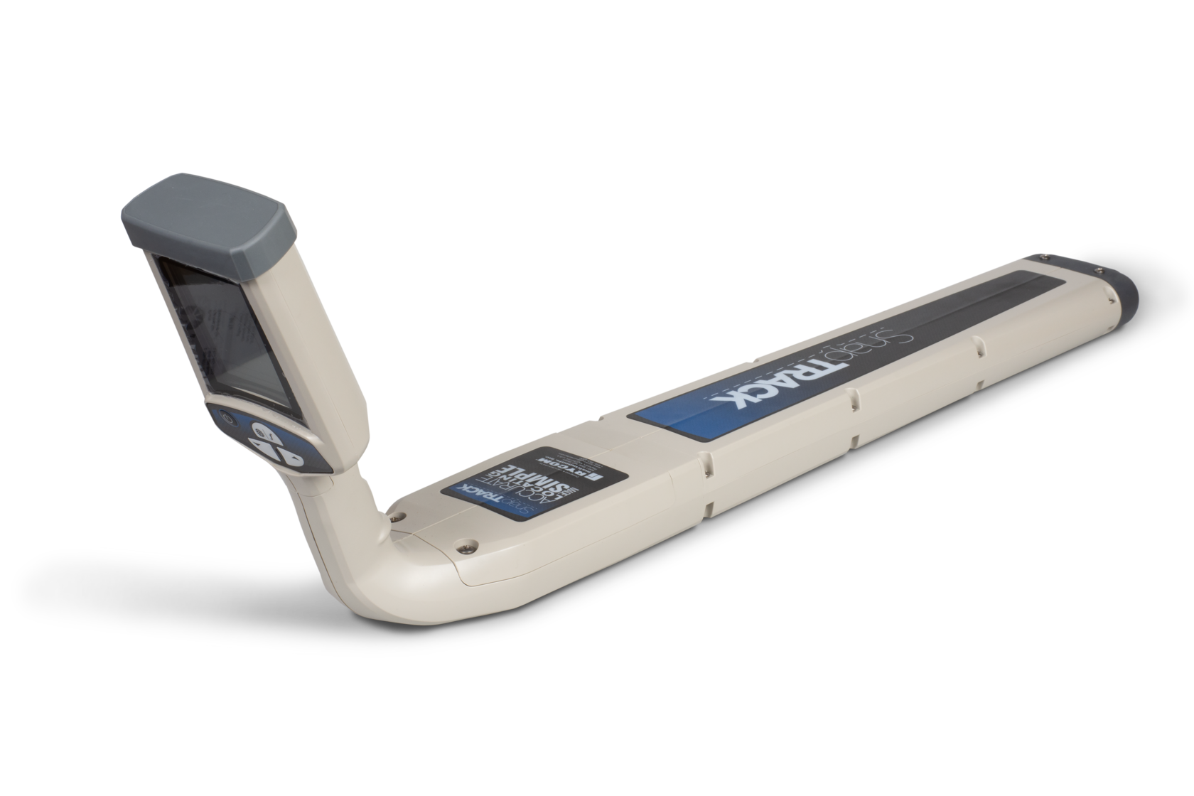
SnapTrack 512Hz Sonde Locator
— Manual triangulation for depth measurement
—Weight: 3 pounds
— Audio and Visual Indications
— Operates on 512Hz frequency mode
— Passive detection of 50Hz or 60Hz, and sonde
— One-button digital depth measurement
— Weights under 2.8lbs
— Audio & Visual Indication Outputs
— Battery & Sensitivity Indicators
— Small for easy storage
— Battery Life: 12 hours (intermittent use)
— Peak and null readings for exact pinpointing
— Max depth reading: Typical 5-8' (1.5 - 2.5 m) dependent on signal level emitted by sonde
— Made in the USA
SnapTrack 512Hz Sonde Locator
— 512Hz / 640Hz Low frequencies
— Optional 815Hz and 33kHz locating modes— Manual triangulation for depth measurement
—Weight: 3 pounds
— Audio and Visual Indications
— Battery Life: Continuous 40 hours, Intermittent 82 hours (10-minute auto shut off)
— Signal Strength: LCD bar graph, Absolute Signal Strength readout 0-999
— Operating Temperature: -4°F to 133º (-20ºC to +55ºC)
—Made in the USA
How to Use a Sonde Locator
XT512 Sonde Locator Introduction
Snap 512Hz Sonde Locator
Locating a Sonde Beacon | Basic Principles
Using a Sonde Locator for detecting a sonde from underground or in the wall
The main steps of locating a sonde beacon that is integrated into a sewer camera or connected to a push rod come down to knowing the approximate location of the sonde, detecting the emitted waves, narrowing down the wave funnel, and pinpointing the position of the sonde. A sonde beacon with a specific wavelength(in this case, 512Hz) has a limited reach area, so the location will always be relative. Another great tip to remember is to match the wavelengths of the sonde and the locator so they are the same.
Steps to Locating a Sonde Beacon:
Steps to Locating a Sonde Beacon:
- Power on the sonde beacon - if the sonde is integrated into the sewer camera head or pipe crawler, it should start emitting waves after powering on the unit; otherwise, there would be a button on the control box.
- Insert the sonde beacon into the desired pipe. Generally, the sonde beacon is used to locate blockages or map out pipelines.
- Power on the Sonde Locator and ensure it is set on the same wavelength as the Sonde beacon. Make sure that the locator is in the sonde locating mode if other modes exist.
- The sonde emits waves that come out of one end and enter into the opposite end, making an oval-shaped curve. Right out of the oval wave shape, there are the Null Points where the signal is the weakest; after the Null Points even further out, there are the "ghost" points where the signal has a bit more strength. In the oval wave shape right above the sonde beacon is the Peak Point, where the signal is the strongest. Once the locator reads the strongest signal, which is confirmed by moving the locator back and forth where the signal is weaker, it means that you are right above the sonde.
- Put the locator into the highest sensitivity, position it in the approximate area of the sonde location, and start moving with the sonde locator parallel to the pipe, noting the greatest area of signal - remember the Peak Points, Null Points, and the "ghost" points!
- Once you have determined roughly the Peak Points, Null Points, and "ghost" points and have marked them on the ground, lessen the sensitivity of the sonde and narrow down the points to the exact point.
- To check the Peak Point, turn the locator sideways as in this video, and it should show a significant decrease in the signal reading; once again, rotate back, and the signal reading should show max.
- In order to have a depth reading, make sure the locator is at its Peak Point(right above the sonde) and press the depth button. The displayed result is the approximate depth from the end of the locator to the sonde beacon. To double-check the depth reading, lift the sonde locator up to 2" and repeat the measurement. If the result reading has increased by 2", then the depth reading is fairly accurate.
- To prove depth reading, use the following technique: find the two Null points, measure the distance between them, and multiply by 0.7. This will be the correct depth reading.
Write us about your application
and we will recommend the right tool to do the job without spending a fortune!
and we will recommend the right tool to do the job without spending a fortune!

Do you have any questions?
Content Oriented Web
Make great presentations, longreads, and landing pages, as well as photo stories, blogs, lookbooks, and all other kinds of content oriented projects.
Content Oriented Web
Make great presentations, longreads, and landing pages, as well as photo stories, blogs, lookbooks, and all other kinds of content oriented projects.