

Electronic assembly inspection guide
Borescopes for Electronic Assembly Inspection
Choose the right micro camera for PCBs, connectors, wiring and confined electronics by starting with access gap, focus distance, viewing direction, light control and documentation needs.
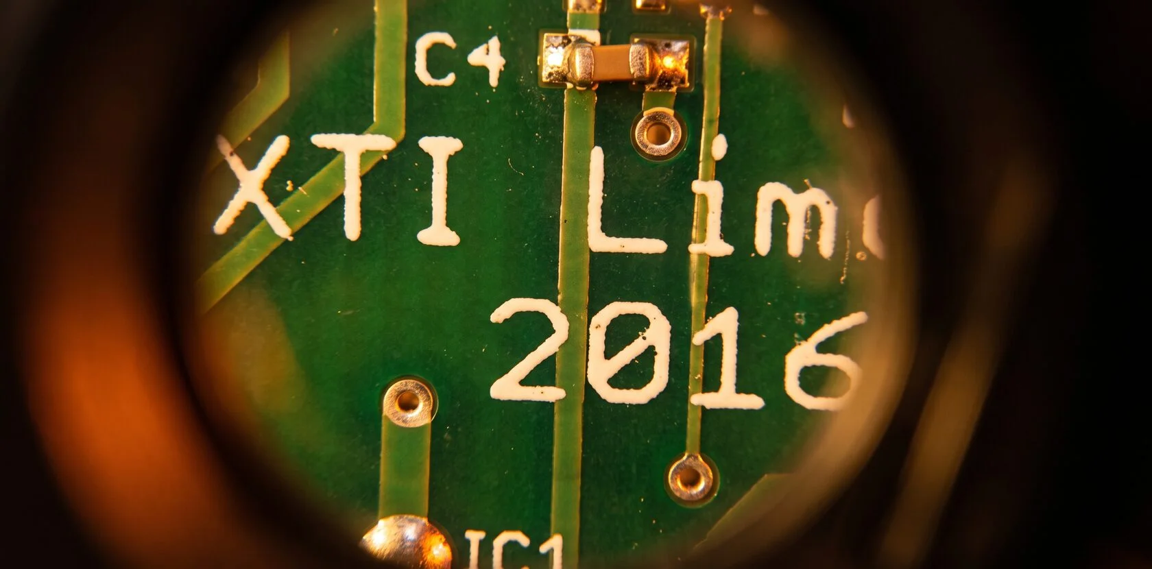
Quick summary
Electronic assemblies can hide defects behind PCBs, cable bundles, connectors and enclosures. Micro-borescopes and small videoscopes help inspect hard-to-reach regions without dismantling the entire product, but the right choice depends on whether the probe can fit, focus, illuminate and view the target without disturbing the assembly.
Why RVI matters
Inspect confined electronics without disturbing the evidence
A suspected defect may sit beneath a cable bundle, behind a PCB, inside an enclosure, behind a connector or near an inaccessible solder joint. Disassembly can be slow and may disturb the evidence. Remote visual inspection gives manufacturers, repair technicians, quality engineers and field-service teams a direct view of accessible hidden areas.
Work through small openings
Use a micro or small-diameter probe when conventional inspection access is not available.
Document what is visible
Capture images or video for QA, rework decisions, supplier discussion and failure analysis.
Reduce unnecessary teardown
Confirm whether a cable, connector, contaminant or visible defect justifies further action.
Best starting point
What borescope is best for electronics inspection?
For many electronic assemblies, the choice comes down to two broad options: a small rigid borescope or rigid video scope for short, straight access; or a micro-diameter flexible or articulated videoscope when the camera must move around boards, wiring, connectors or structural features.
- Small probe diameter: the scope must fit without unnecessary contact.
- Close-focus image quality: focus distance can matter more than megapixel count.
- Controllable illumination: solder, shielding and connector housings can glare.
- Suitable viewing direction: forward, side or articulation may be required.
- Careful probe construction: small does not mean harmless around fragile electronics.
- Image and video capture: useful records need assembly and location context.
Inspection targets
What a borescope can help inspect in electronic assemblies
Connectors and pins
Connector seating, visible connector pins, hidden labels, part numbers and signs of mechanical interference.
Wiring and cable routes
Wire routing, pinched wires, damaged insulation, trapped cables and wiring harness obstructions.
PCB and component position
PCB positioning, displaced components, accessible solder joints, board-to-board gaps and workmanship in inaccessible areas.
Contamination and debris
Debris, foreign material, contamination, corrosion, loose hardware and enclosure damage where visible.
Heat and surface indicators
Accessible heat discoloration or visible signs that may support further testing or teardown decisions.
Simple go/no-go checks
Sometimes the task is simply confirming whether a cable is trapped before taking half the machine apart.
Important limitation
What a borescope does not replace
A visual inspection camera is not a replacement for electrical testing, automated optical inspection where AOI is appropriate, X-ray for hidden solder joints, microscopy for extremely fine accessible surface detail, thermal imaging or functional testing.
- Visible-light RVI cannot see through a package to inspect hidden solder joints.
- A side-view micro-borescope may show package edges, contamination, gaps or accessible peripheral areas.
- Hidden BGA solder-joint questions may require X-ray inspection.
- Thermal anomalies require thermal imaging.
- Circuit function requires electrical test equipment.
Practical challenges
The main challenges in electronic assembly inspection
Extremely small gaps
Conventional industrial videoscopes may be too large. Measure the real gap before choosing a probe.
Very short working distances
The camera may sit only a few millimeters from a PCB, connector or component.
Reflective surfaces
Solder, shielding and plated contacts can overexpose quickly without fine illumination control.
Fragile components
An insertion probe can bend wires, scratch a board, disturb connectors or introduce contamination.
ESD sensitivity
Follow established ESD-control procedures and verify compatibility when required.
Electrical safety
Inspection of energized equipment should be performed only under approved procedures with suitable equipment.
Interactive selector
Start with the electronic assembly inspection scenario
Choose the constraint that controls the inspection. The result is a configuration starting point, not a substitute for checking the real gap, target distance, ESD requirements and approved procedure.
Small rigid borescope or rigid video scope
Useful when the access is short and straight, the target is close, and precise positioning matters.
- Measure: opening size and clearance between components.
- Check: minimum focus distance at the real target distance.
- Document: location before close-up images.
Articulated micro-videoscope
When wiring blocks the path or a connector faces away from the opening, articulation can help aim the view without disassembly.
- Verify: probe diameter and bend path.
- Avoid: using the probe to move wires or connectors.
- Use: low force and ESD-controlled handling.
Side-view optics or articulated tip
Side view can be better for PCB faces, connector sides and board-to-board gaps that run parallel to the probe.
- Choose: forward or side view based on target orientation.
- Confirm: depth of field at close range.
- Record: orientation so the image is understandable later.
Close-focus optics with fine illumination control
Reflective solder and metal connector housings can overexpose quickly. Useful control matters more than maximum brightness.
- Start: with low illumination.
- Adjust: light to preserve contrast.
- Compare: context and close-up views.
Features to compare
Features to look for in an electronics inspection borescope
- Micro probe diameter: fit without unnecessarily contacting sensitive components.
- Close-focus performance: check depth of field, not just resolution.
- Forward vs. side view: match viewing direction to connector, PCB or gap geometry.
- Rigid vs. flexible probe: choose based on route, target direction and positioning control.
- Low-glare illumination: use controlled light for reflective solder and contacts.
- Image and video capture: document the assembly and location, not just the close-up.
- Clean probe construction: avoid introducing contamination into the assembly.
- ESD and procedure fit: follow the facility controls and verify compatibility when required.
Selection guide
Electronics borescope selection guide
| Inspection situation | Recommended approach | Decision point |
|---|---|---|
| Narrow straight gap between boards | Small rigid borescope | Precise positioning and fit through the gap |
| Hidden connector around an obstruction | Articulated micro-videoscope | Ability to aim behind wiring or structure |
| Very small enclosure opening | Ultra-small probe | Probe diameter is the limiting factor |
| PCB surface beside probe | Side-view optics | Target runs parallel to the insertion path |
| Reflective solder or shielding | Fine illumination control | Reduce glare and preserve contrast |
| Very short camera-to-target distance | Close-focus or macro-capable optics | Focus at actual working distance |
| QA documentation | Still/video capture | Capture context and detail |
| Hidden BGA solder joint | Appropriate X-ray inspection | RVI cannot see through the package |
| ESD-sensitive assembly | Follow ESD controls and verify compatibility | Do not assume the scope is ESD-safe |
Three-step process
A three-step selection process for electronics
Measure the smallest gap
Determine opening size, clearance between components, insertion length and target distance. Do not assume; measure.
Define what must be visible
Connector seating, pinched wire, contamination, solder joint, corrosion or shifted component each requires different focus, view and detail.
Determine viewing direction
If the target faces the opening, forward view may be ideal. If the surface runs parallel to the probe, side view may be better.
Method comparison
Borescope vs microscope vs X-ray for electronics inspection
| Inspection requirement | Best starting technology | Reason |
|---|---|---|
| Inaccessible but visible surface | Borescope or videoscope | Remote visual access through a gap or opening |
| Accessible very fine surface detail | Microscope | Surface is reachable and requires high magnification |
| Hidden BGA or internal solder joint | X-ray | The joint is not physically visible to a camera |
| Circuit function | Electrical test equipment | The question is functional, not visual |
| Thermal anomaly | Thermal imaging | The evidence is heat pattern rather than visible surface condition |
| Hidden wire or connector position | Borescope or videoscope | The camera can confirm accessible routing or position |
Suggested products
Recommended borescope platforms for electronic assembly inspection
These product families cover different access and inspection situations. Confirm probe diameter, focus range, viewing direction, illumination control, ESD-related requirements and suitability for your assembly before selection.
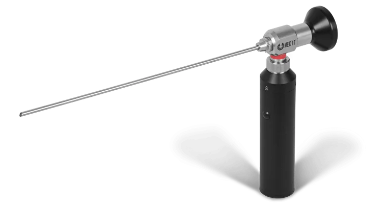
MEDIT Rigid Borescope
For short, straight access into enclosures, board gaps or connector areas where rigid positioning and viewing direction fit the target.
View product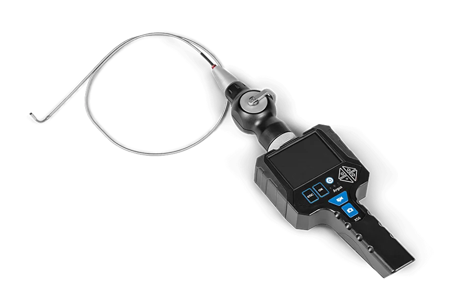
Rigid Video Borescope ORION
A rigid video option for short, accessible electronic assembly checks where direct digital viewing and capture are preferred.
View product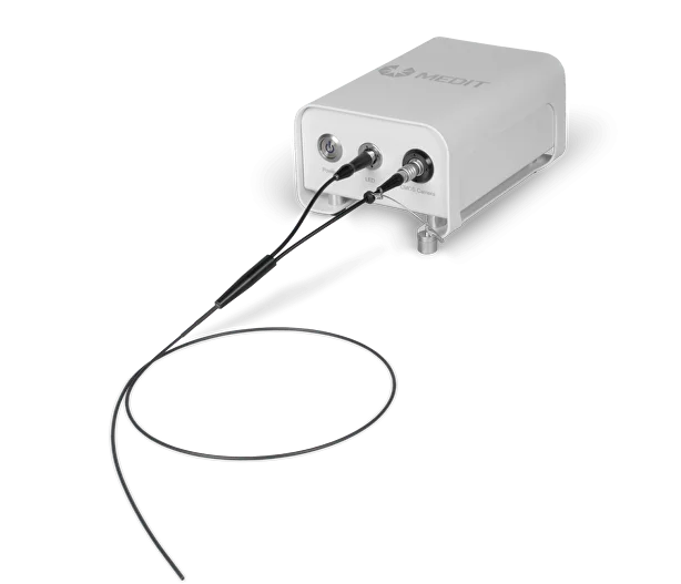
USB Micro Borescope MICRON
A micro-borescope option for very small openings, narrow board gaps and confined electronics where conventional 4-6 mm scopes may not fit.
View product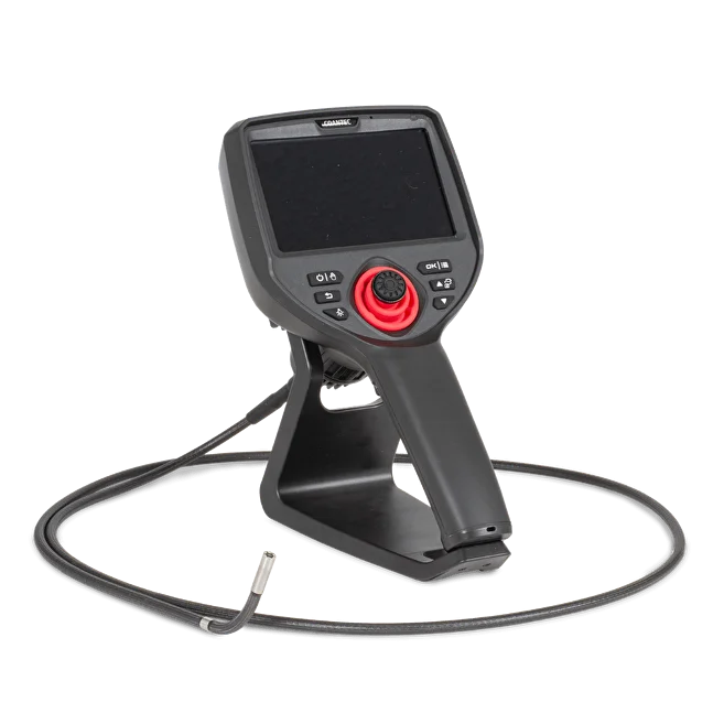
VOYAGER M40 HD Borescope Camera
A flexible inspection platform to compare when wiring, connectors or internal structure make the route more complex.
View product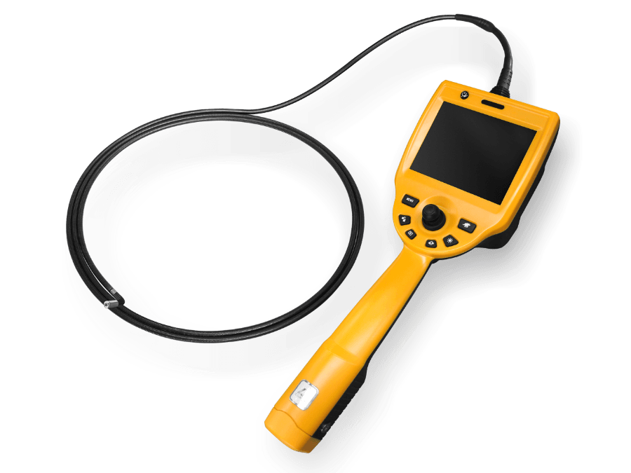
VOYAGER C50 Video Borescope
A video borescope option for visual documentation, review and shared inspection evidence in electronic assembly work.
View product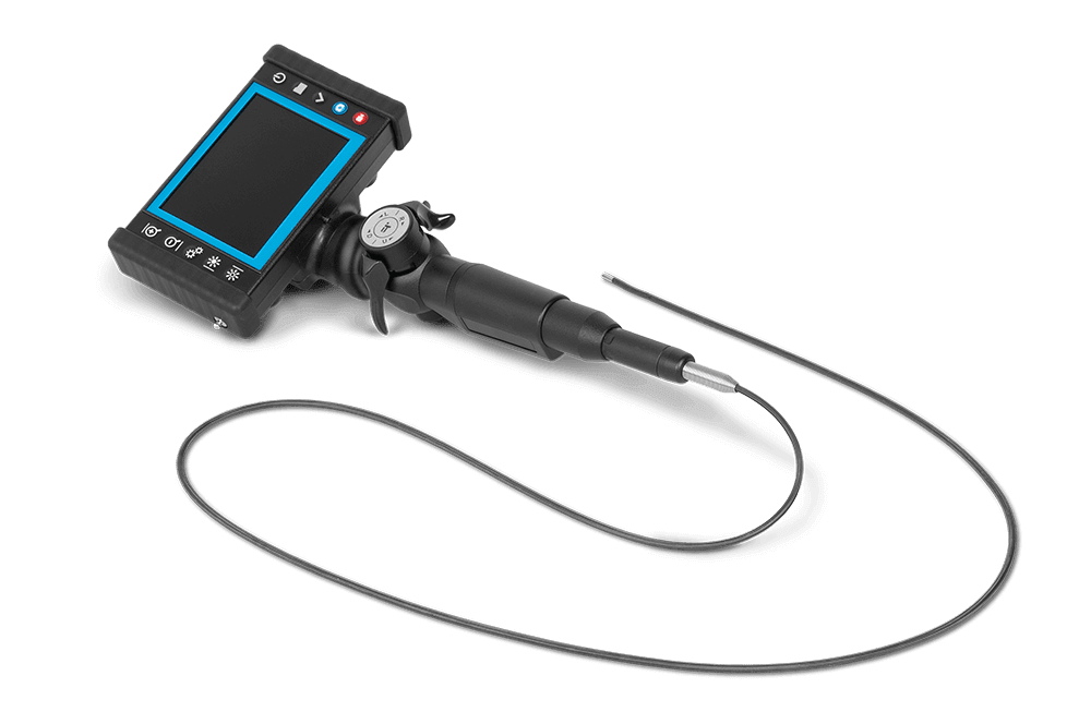
VIDEOSCOPE-XT
An explosion-proof product family to evaluate only when the electronics inspection location requires certified equipment for a classified area.
View product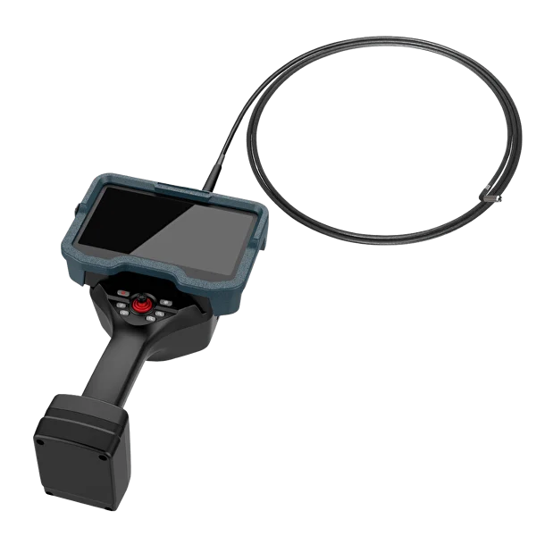
NEXUS X5 3D Stereo Measurement Videoscope
A measurement-capable platform to consider when a visible feature must be dimensionally characterized rather than simply documented.
View product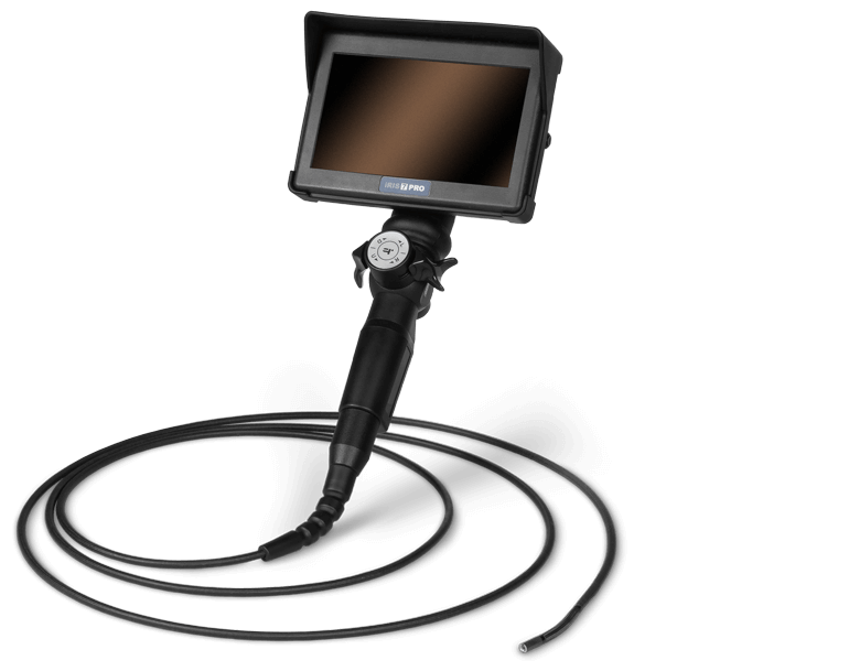
IRIS PRO Industrial Videoscope
An industrial videoscope option for articulated inspection and image or video documentation where probe size and access are suitable.
View product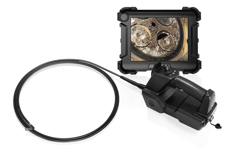
VOYAGER C68HD
An industrial video borescope platform to compare for demanding internal visual inspections when access and handling constraints allow.
View productImage samples
Image samples from borescope inspection systems
Video samples
Inspection footage and demonstrations
USB Camera with Rigid Borescope | Metal Casting Inspection
IRIS DVRx Videoscope 4mm | Video Capture Sample
IRIS PRO Industrial Videoscope | Metal Part Inspection
Digital Micro Borescope MICRON | Small Part Inspection
Better practices
Better practices for electronic assembly borescope inspection
Electronic assemblies are small, reflective and fragile. The inspection process should protect the assembly while creating a record that can be understood later.
- Start with low illumination; reflective solder and contacts can overexpose very quickly.
- Never use the probe as a lever or push wires, connectors or boards with the camera tip.
- Use the same ESD controls you would use for other electronics-handling work.
- Capture both context and detail: one image should show where the condition is, another what it looks like close up.
- Keep the inspection record tied to the assembly, access point, target and location.
FAQ
Electronic assembly borescope questions
What borescope is best for electronic assembly inspection?
Why does probe diameter matter so much in electronics?
Is the smallest probe always the best choice?
Can a borescope replace X-ray for hidden BGA solder joints?
What is important besides image resolution?
What safety precautions matter for electronics inspection?
Should electronics borescope inspections be documented?
Final recommendation
Send the access gap and target distance before choosing a camera
For electronics, optical geometry matters more than impressive-looking specifications. Send Fiberscope the enclosure dimensions, smallest access gap, target distance, required viewing direction and a photo or description of the assembly. That information makes it easier to narrow the appropriate micro-borescope, rigid scope or articulated videoscope.